I wanted some metal tread to print and use as basing material for my orks. Being a software engineer at heart, I tried to build something reusable with geometry nodes. This post is going to be part here’s something fun I did and part documentation so I remember how I did it.
This is the kind of result I’m looking for. This is a photo from the sprue of my Deffkilla Wartrike.
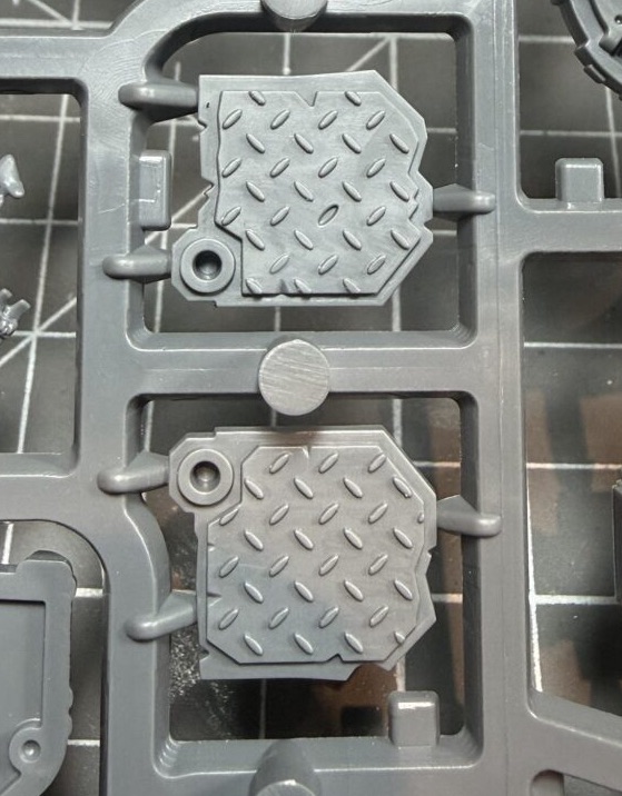
It would be cool to replicate the nicks, scrapes, and damage. But for now I’m just going for a nice boring square of texture:
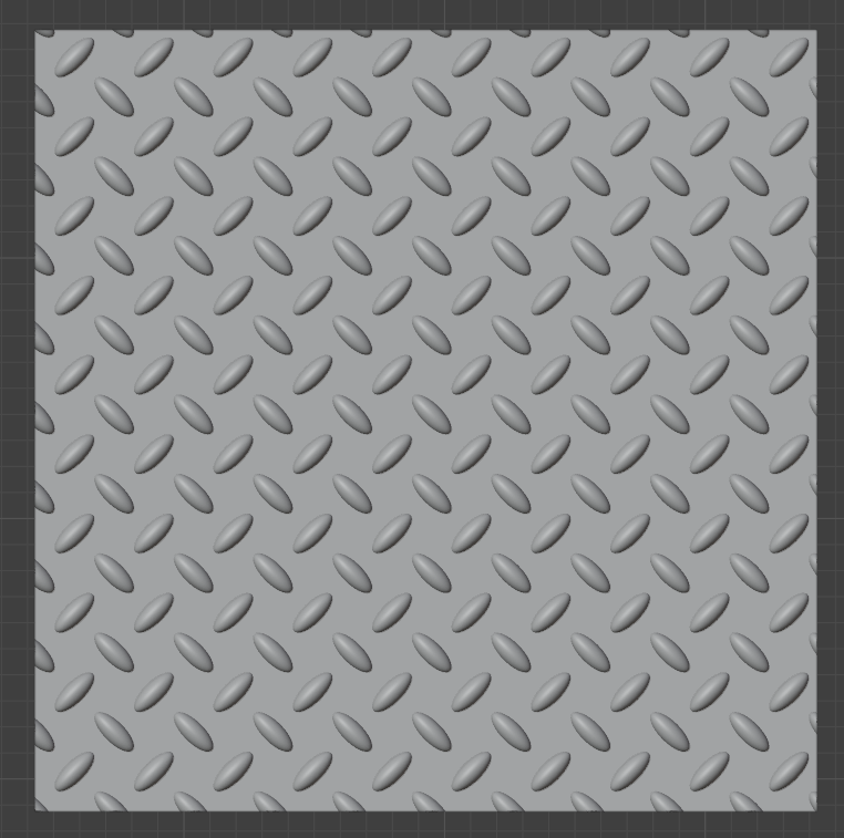
We start with a 30mm x 30mm plane (Shift-A > Mesh > Plane). Then we add a geometry node modifier to it.
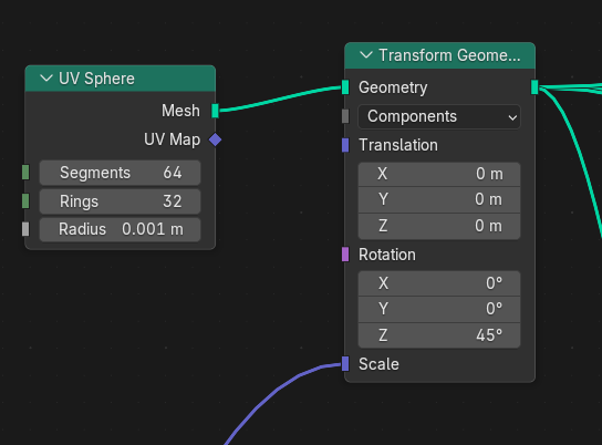
I added a 1mm UV Sphere for the tread, and put it through parameterised scale transform so that we can easily control the shape of our little blobs.
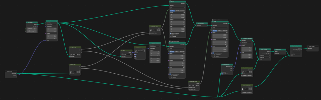
Next we need to pass this through three array nodes. We’re going to construct the grid by first making two columns: one for each rotation of the blob. Then finally we copy those two columns across the width of the plane to make our rows.
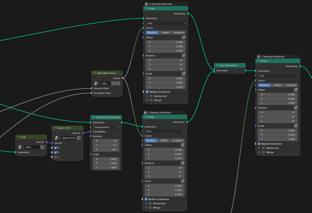
The important bits here are that the offset is 2 on the Y axis, that gives us the right spacing between blobs. But we also have to shift the second column by the (X and Y) size of the blob to give us the staggering between the two columns. Think of this as an initial offset before we apply the array offset to each element.
Note that we also do the rotation here, our first transform rotated the blobs by 45°, so the second column just takes that and rotates it back 90°.
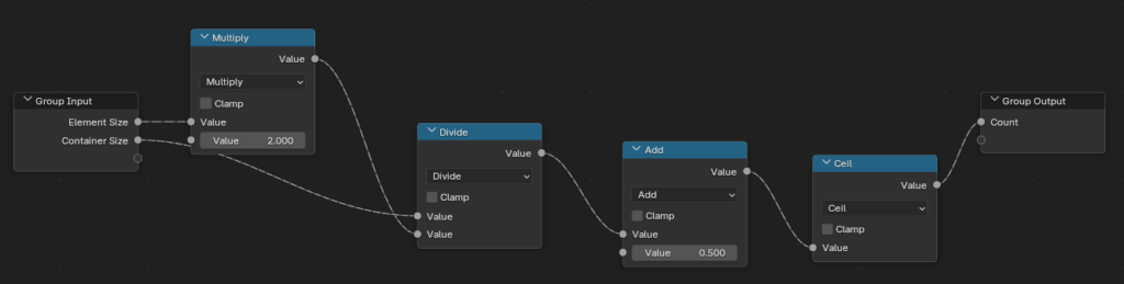
We also need to calculate the array counts, which is just a little bit of maths on the bounding boxes of the plane and the blob. I wish we had math expression nodes to make this kind of thing easier (and it looks like that might happen in the future).
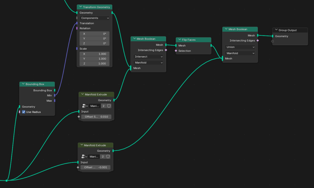
Finally, we need to do some mesh booleans. Firstly we intersect our array with an extrusion of the plane to cut off and cap the blobs on the edge of the square. Then we union our blobs with a backwards extrusion of the plane for our final shape.
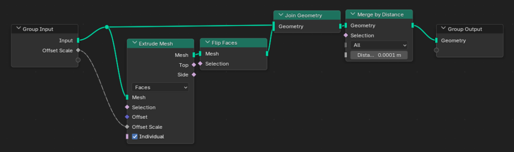
The extrusions themselves are a bit annoying because the ‘Extrude Mesh’ node doesn’t give a manifold mesh, so I added this group node merge the original plane into the (flipped) extrusion:
Here’s a map of how it all fits together:
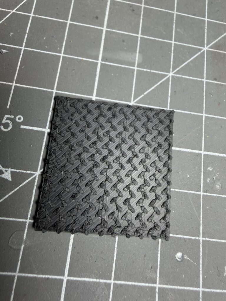
So far I’ve only tried to FDM print this, and unfortunately it doesn’t look great. I did this with 0.4mm nozzle (I should probably swap it out for 0.2mm), and I think my filament is a bit wet. But I think I’ll wait until I have a batch of basing bits ready and pull out my resin printer. Here’s a picture anyway: